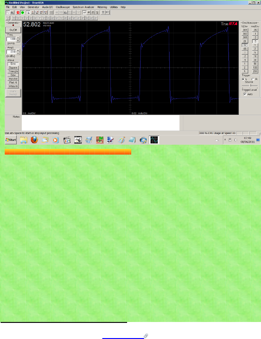

If the output voltage is 10VAC and you apply a resistor network or line output converter that takes it down to 1VAC you have a ratio of 10:1. Also be sure to note that your DMM measures average or RMS voltage and your scope easily displays peak voltage, refer to the attached image. If the voltage needs to be reduced, keep track of the ratio (output : input) so you can translate the results. To determine the output voltage of your circuit or device (if you don't know it already) you should measure it with a volt meter to determine both the AC and DC voltage characteristics.

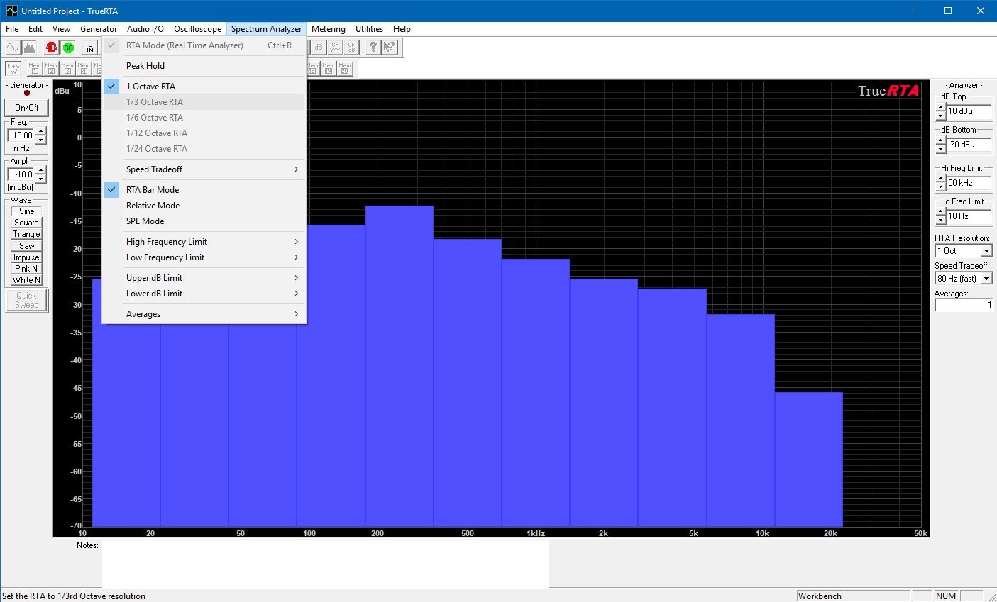
You want to take frequency ranges into consideration because some transformer-based line output converters will affect frequency response. The line output converter takes speaker level signals and reduces them down to line level signals through resistor networks or an audio transformer. If you are looking at the output of an audio amplifier, a line output converter is a perfect device for this purpose. This can be done with a voltage divider resistor network or a line output converter circuit or device. DO NOT EXCEED THE INPUT VOLTAGE RANGE! This means that circuits with higher output voltages will need to reduce that voltage down to an acceptable level. The input to most computer sound cards is fairly low, only a volt. In order to use a computer-based real time analyzer (RTA) to measure the electrical behavior of your circuit, you need to determine what voltage range your circuit will produce. Images include the setup bench and a block diagram of signal routing. The embedded video offers a narrative explanation of the process. If you want to make something sound better that it does from the factory, it is helpful to know what you're working with. Measuring the frequency response of audio amplifiers and determining if there are filters in the system - this is useful when determining what the signal looks like in OEM/Factory audio systems (cars, stereos, etc.).Troubleshooting circuits by looking at both voltage and frequency components.This also provides a good way to test clipping detectors by tracking the conditions that trigger the circuit. Viewing the onset of signal clipping (exceeding voltage rails or range) and the harmonics associated with clipping.Viewing and storing frequency response outputs.Viewing and storing oscilloscope outputs or traces.Viewing the output of a circuit before or after noise filters, or just looking for noise itself.This is helpful for custom speaker designs with custom passive crossovers. Viewing the actual effect of passive crossovers or filters to see what their exact effect is.This is good for identifying the harmonic content in a signal, any high-frequency noise content, and also to determine the effects of filters. An RTA gives a view of the frequency spectrum of the signal under test.


The primary benefit to this approach over an oscilloscope is that RTA programs can function as both an oscilloscope for seeing voltage as well as an RTA for seeing frequency response.Īn oscilloscope is good for simple tones, but complex signals are difficult to discern. The purpose of this trick is to give viewers and affordable option to view the electrical signals of their circuits and devices using real time analyzer (RTA) programs.


 0 kommentar(er)
